Results
After the optimization has been completed you are able to analyze the results using various reports and breakdowns from the supplier to the customer.
Next we discuss these options in turn.
Main Map
The map presents the optimal flows through the network for the selected period. By default, the table shows the data for the first period. The nodes are color-coded based on the their type.
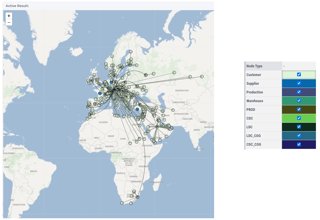
The arcs show the different types of transportation lanes, so, the color and the curve are based on their types:
Primary (curved, blue): Flows go from Suppliers and represent “the first mile” flows.
Secondary (straight, olive): Flows go to Customers and represent “the last mile” flows.
InterResource (curved, black): Flows go between Resources (Production facilities, Warehouses, etc.).
Direct (straight, olive): Flows go directly from a Supplier to a Customer.
When hovering over one the lanes or over one of the nodes on the map a tooltip appears for that lane or that node:
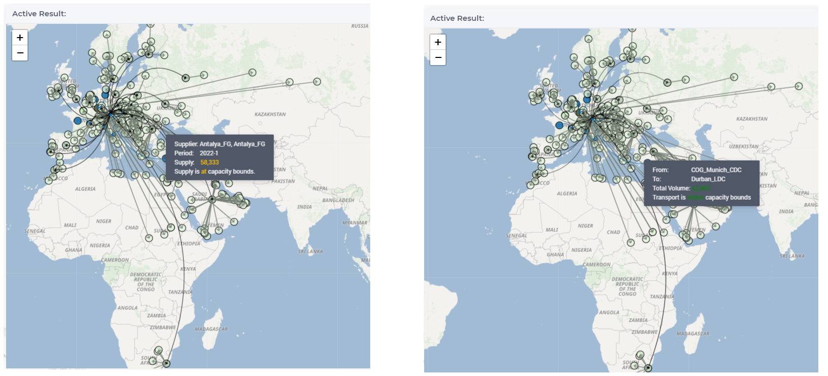
Please note that an arc is only displayed on a map if either its start node or its end node is currently in view. This ensures that no ‘loose’ arcs are visible, for which it is unclear from/to where they flow.
Zooming
To zoom in or out of any map in SC Navigator, there are various options to do it. For the best experience, it is good to be aware of the following:
To zoom the map to a custom rectangle, please press the SHIFT key and keep it pressed when selecting a rectangle on the map by dragging your mouse. When releasing the mouse button, the map immediately zooms to your selected area.
To zoom in a fine-grained manner, either use the + or - button in the top left corner of the map, or use your mouse wheel.
To zoom using more coarse steps, hold SHIFT when using the + or - button in the top left corner of the map.
Besides these zoom techniques, you can of course also drag the map along with your mouse to move it to the required position.
Customization Settings
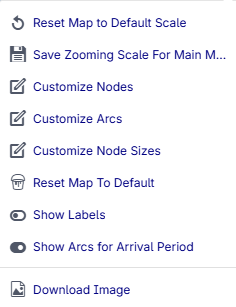
You can customize the map by clicking on the menu icon  at the upper right side of the map widget. You can perform the following actions:
Reset Map to Default Scale: After zoom in or zoom out on the map, you can reset the map to the default zooming state by clicking on the Reset map to default scale option.
Save Zooming Scale for Main Map: After zoom in or zoom out on the map, you can save the actual zooming scale so when you open the application the map will be set to this zooming scale.
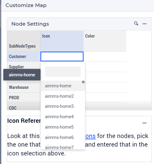
Customize Nodes: You can customize the icons and the colors of the nodes by clicking on this option. After customization, when you open the application the nodes will be displayed accordingly. For the icons, you can choose between a list of standard AIMMS icons and a list of SC Navigator-specific icons. For the colors, you can choose a standard color or one of your own, see Custom Colors.
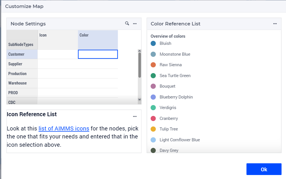
You can select icons or colors by clicking twice on the appropriate cell in the table and select the icon or the color from the list.
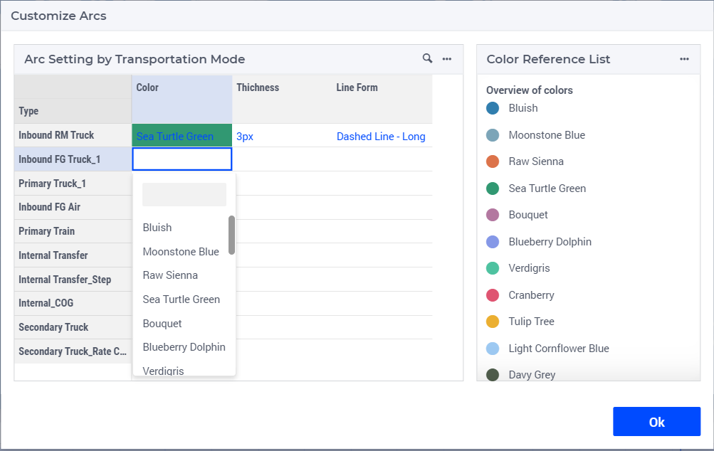
Customize Arcs: You can customize the color, thickness, line form of the arcs. After customization, when you open the application the arcs will be displayed accordingly. For the colors, you can choose a standard color or one of your own, see Custom Colors.
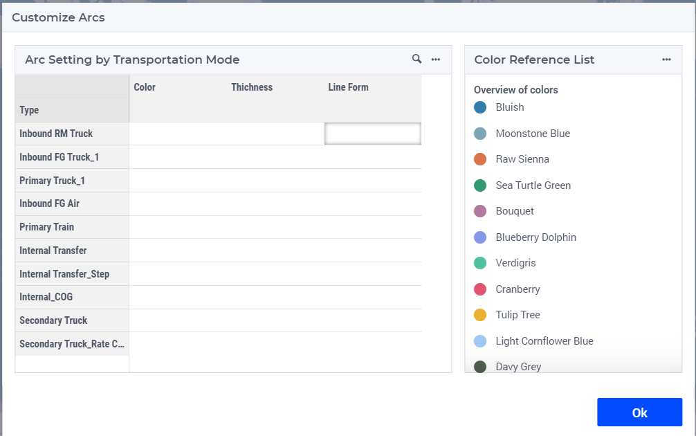
You can select color, thickness, line form by clicking twice on the appropriate cell in the table and select from the list.
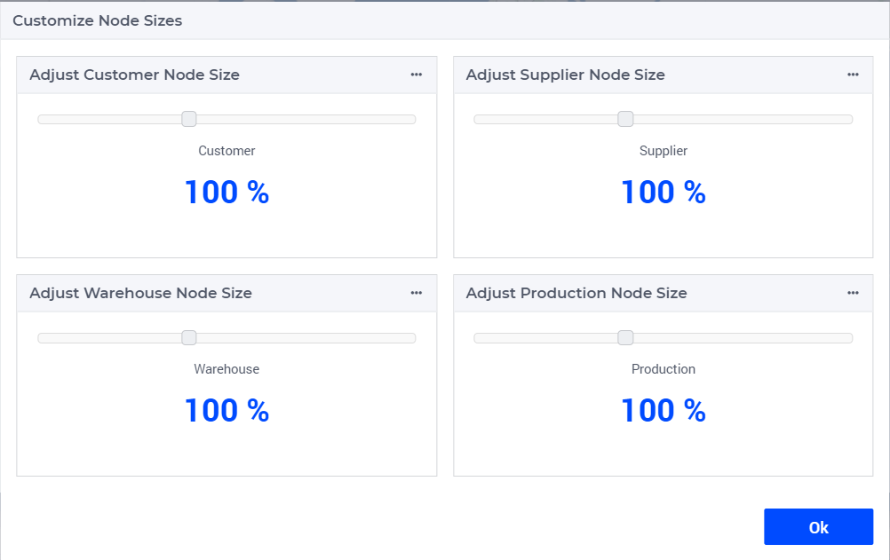
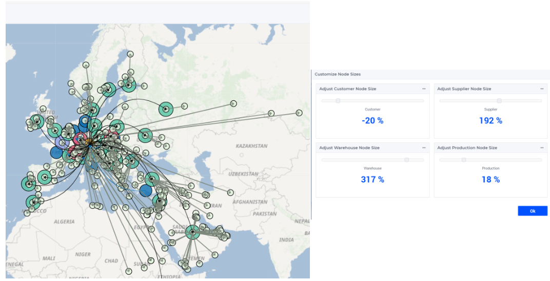
Customize Node Size : You can set here the size of the supplier, production, warehouse and customer nodes. After customization, when you open the application the nodes’ size will be displayed accordingly. By default it is 100%. You can change the size by moving the slider to the right (increase) or left (decrease). The size can be decreased to -100%, and increased without an upper limit.
Reset Map to Default: You can set the map by the default setting by clicking on this option, but when you reopen the application the customized setting will be applied. Your own colors are kept; only the choices you made for the nodes and the arcs are reset.
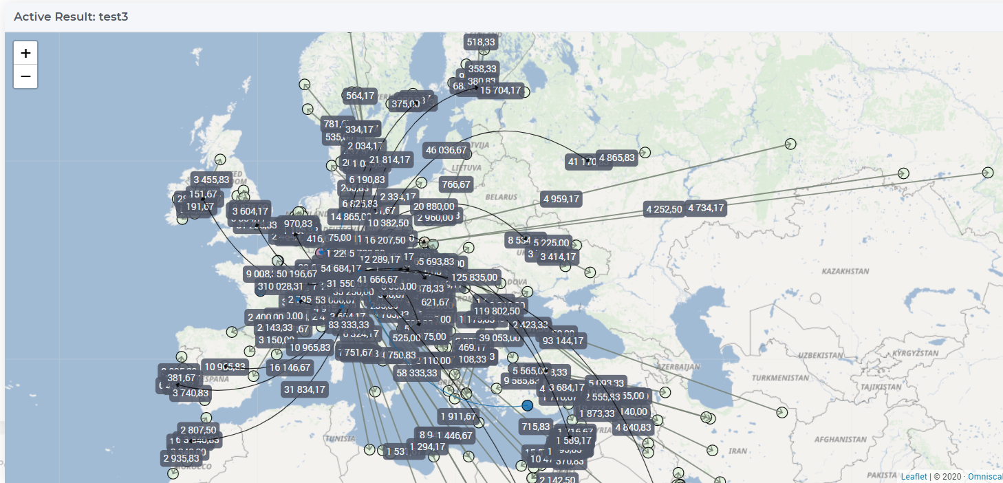
Show Arc Labels: Shows or hides the volume labels on the lanes.
Show Arcs for Arrival/Departure Period: see details in Lead Time Offset.
Custom Colors
Besides the standard colors, you can define colors of your own and use them for the nodes and the arcs. Custom colors are shared with everyone working in the same environment, so a color you add is available to your colleagues as well.
In the Customize Nodes or Customize Arcs dialog, click the menu icon of the list of colors and choose Manage User Colors.
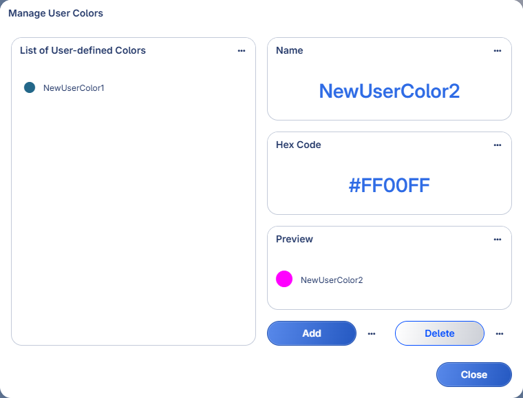
Adding a color: Enter a name and a hex code, for example
#2ECC71, and click Add. The hex code must be a#followed by six hexadecimal digits, and the name may not contain quotes or backslashes. A name already used by a standard color is not accepted. If the name is one of your own colors, you are asked whether to overwrite it.The Preview box shows the color once you have entered a complete hex code and confirmed it, by pressing Enter or by leaving the field. It stays empty as long as the hex code is incomplete.
Changing a color: Click a color in the list to copy it into the fields, adjust the hex code, and click Add to overwrite it.
Deleting a color: Click a color in the list, or type its name in the Name field, and click Delete. The name in the Name field is the one that is deleted. You are always asked to confirm, because the color is removed for everyone in the environment. The question tells you how many node types and transport types you have set to it; those fall back to their default color. It cannot tell you what your colleagues have set to it, so a color may be in use even when the question says you are not using it yourself.
After adding a color it appears in the color lists of the Customize Nodes and Customize Arcs dialogs, where you can select it like any standard color. Custom colors are used on every map that offers these dialogs: the main map and the reference map on the Results page, the map on the Center of Gravity page and the map on the Transport Navigator page.
Note
Colors added, changed or deleted by a colleague are picked up when you next open one of the customization dialogs, or when you open one of these map pages again. They do not change while you stay on the same page.
Filters
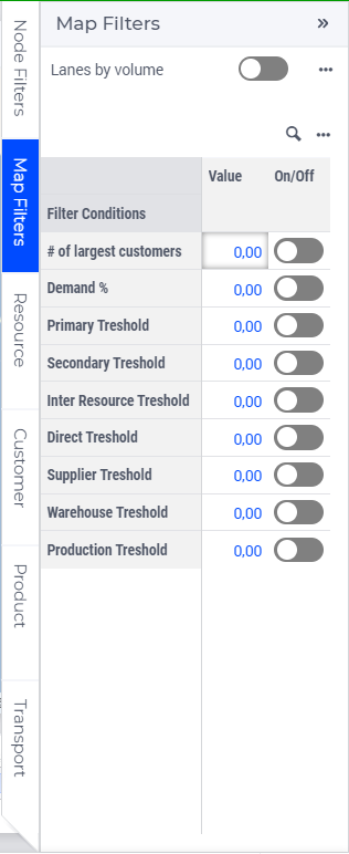
On the Filters side panel you can turn on the Lanes by Volume option and you can apply filtering conditions, such as:
Number of Largest Customers: You can define the value of how many of the customers (sorted by demand) should appear on the map. For example, if the value is 3, the three largest customer will be shown on the map.
Demand %: You can define the value of what percentage should be displayed on the map. For example if the value is 10%, the customers whose total demand is the 10% of the all defined demand will be displayed on the map.
Primary Threshold: You can define a value at which primary lanes with greater volume will be displayed on the map. For example, if the value is 2000, then the map will show only those primary lanes which volume is greater than 2000.
Secondary Threshold: You can define a value at which secondary lanes with greater volume will be displayed on the map. For example, if the value is 2000, then the map will show only those secondary lanes which volume is greater than 2000.
Inter Resource Threshold: You can define a value at which inter resource lanes with greater volume will be displayed on the map. For example, if the value is 2000, then the map will show only those inter resource lanes which volume is greater than 2000.
Direct Threshold: You can define a value at which direct lanes with greater volume will be displayed on the map. For example, if the value is 2000, then the map will show only those direct lanes which volume is greater than 2000.
Supplier Threshold: You can define a value at which suppliers with greater supply will be displayed on the map. For example, if the value is 2000, then the map will show only those suppliers whose supply is greater than 2000.
Warehouse Threshold: You can define a value at which warehouses with greater volume will be displayed on the map. For example, if the value is 2000, then the map will show only those warehouses whose volume is greater than 2000.
Production Threshold: You can define a value at which production facilities with greater production will be displayed on the map. For example, if the value is 2000, then the map will show only those production facilities whose production is greater than 2000.
Node
Nodes are the geographic locations represented on the map. On the Node side panel you can set filtering options for nodes. Node Types are usually divided into Customer, Supplier, Production, and Warehouse. For Production and Warehouse several groups are shown. Please note that only the nodes of the selected types will be displayed on the map. Customer nodes will be filtered by default when more than 2500 customer locations are present in the input data.
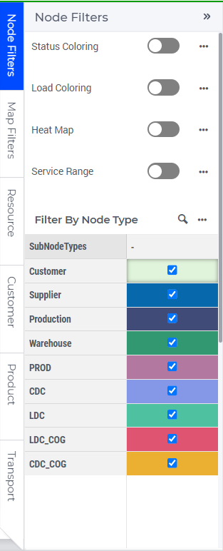
This selection works different than other filters. Normal filters allow you to select both group and individual elements, this filter only shows groups. The behavior is as follows:
A location is shown on the map only if ‘Show Node’ is checked for every group that contains that location.
Groups for which only part of the locations are shown have a gray background in the checkbox, and a tooltip to indicate that only some of the related locations are shown.
If you (un)select one of the four standard elements (Customer, Supplier, Warehouse, Production), it will (un)select all the groups of that type.
The table only shows an icon for groups that have single node type. If a group has multiple node types (like customers and warehouses), no icon will be shown.
Elements that don’t belong to any group, can be shown by unchecking every subgroup, while keeping the related standard element checked.
Checking the ‘Show Label’ checkbox for a group will show the node labels for all locations in that group.
There are also several other kinds of coloring for the nodes, which you can set in this side panel:
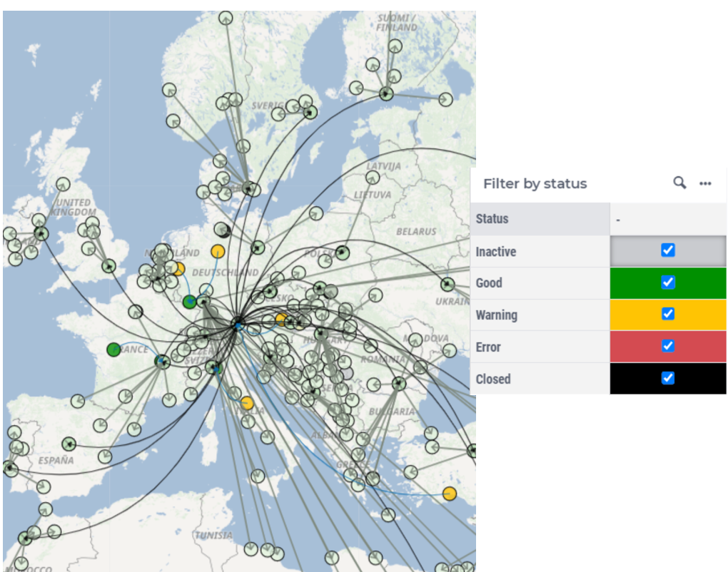
Status Coloring: The supplier, production and warehouse nodes will be colored based on their status. The meaning of the colors:
Red (Violated): when the capacity utilization is higher than its limit
Orange (Near bounds): when the capacity utilization is close (above 95%) to its limit
Green (Within bounds): when the capacity utilization is within its limits
Gray (Inactive): when the supplier/production/warehouse is not active
Black (Closed): when the supplier/production/warehouse is closed by the model
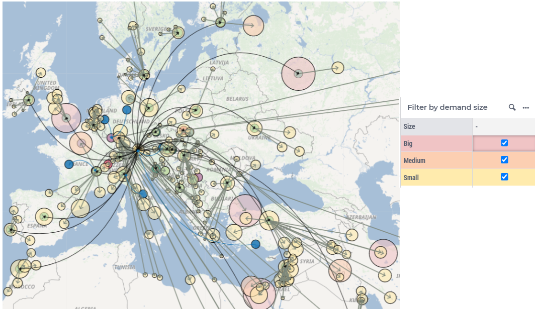
Load Coloring: The customer nodes will be colored based on their demand. The customers are sorted in three groups based on their volume: big, medium and small.
Heat Map: Heat Map can be used to visualize demand distribution, but for a good overview, more than 1000 nodes are needed.
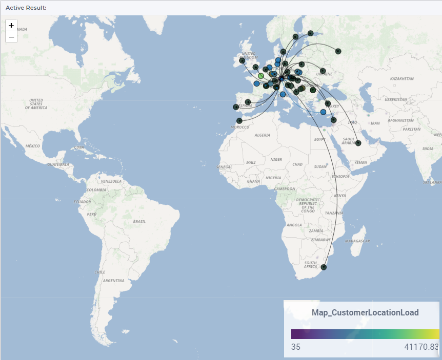
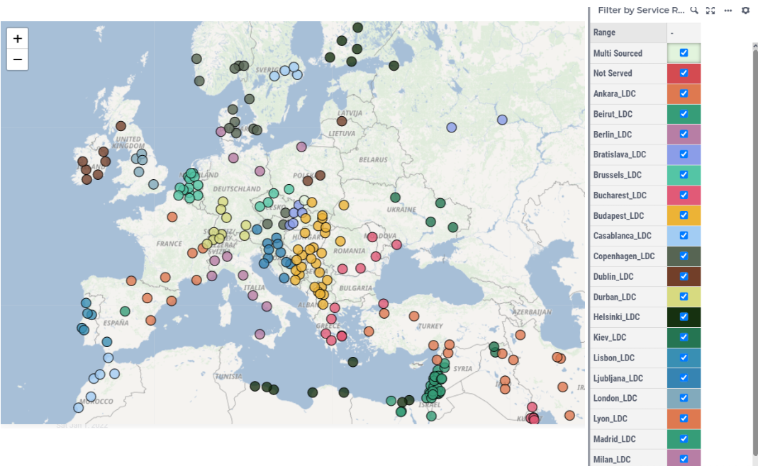
Service Range: The customer nodes will be colored based on the supplier/warehouse that shipped to the customer.
Customer Reallocation
The Customer Reallocation feature allows you to interactively change which sources serve specific customers by directly modifying the Force Open/Close data from the Main Map. This process involves two main steps:
Modify Assignment Constraints by choosing Force Open/Close constraints.
Re-solve the model using the updated constraints, optionally keep the existing open/closed facilities unchanged.
Modify Customer-Source Assignments
The Customer-Source assignments can be modified by opening the Customer Reallocation dialog. There are two ways to open the Customer Reallocation dialog:
- Right click on a customer node.
The customer must have one or more transport lanes connected to warehouses or suppliers.
The dialog will display all possible lanes this customer can connect to, across all products and periods.
- Right click on a Secondary Transport lane.
The dialog will display the selected lane across all products and periods.
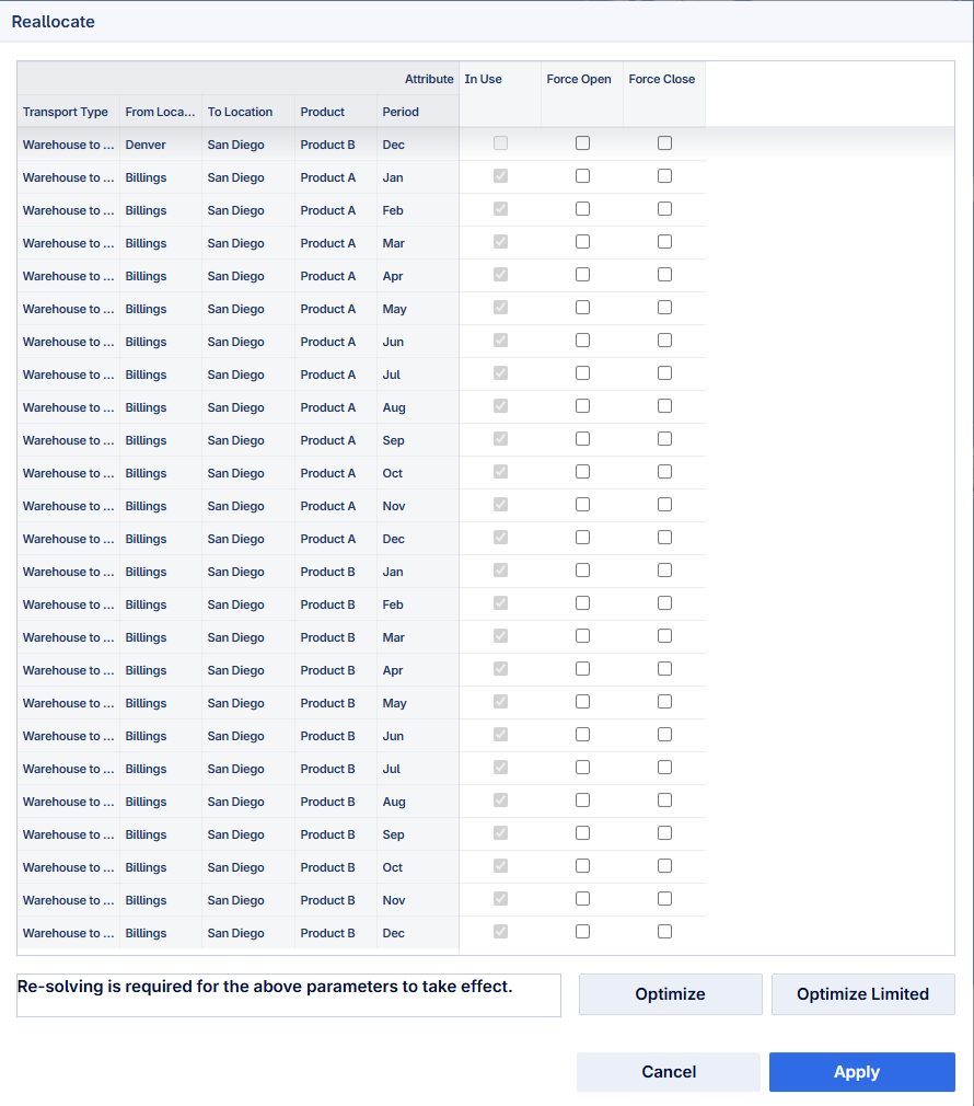
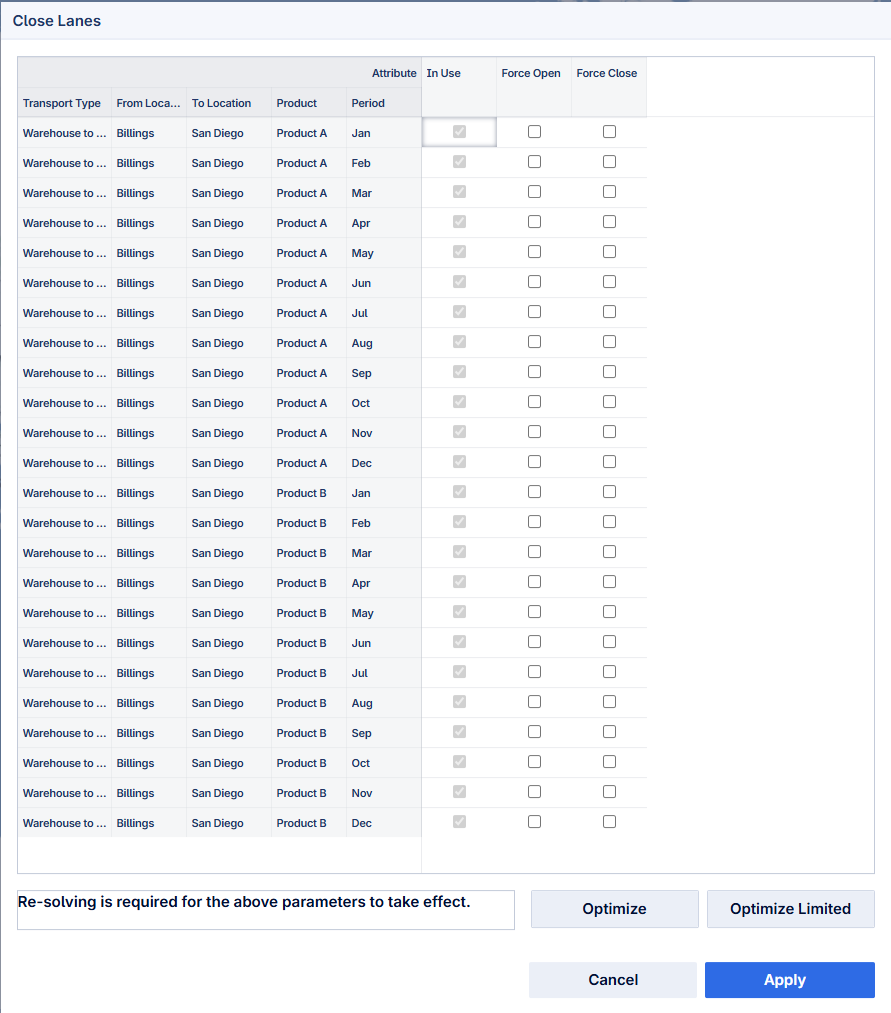


Dialog Table Columns:
In Use – Indicates the current assignment status.
Force Open - Forces the associated transport lane to remain open.
Force Close - Forces the associated transport lane to remain closed.
Behavior:
Selecting Force Open automatically deselects Force Close (and vice versa).
Changes are not applied automatically.
Click Apply to apply changes to Force Open/Close data. The updates appear in the Data pages, and you can continue reallocating other customers/lanes.
Optimize and Optimize Limited buttons automatically apply changes before solving.
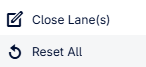
To reset all customer/lane changes, use the right-click option Reset All.
Re-solve the Model
After modifying assignments, there are two modes to re-run the optimization via the Reallocation dialog. Note the implications of each mode:
Optimize
Enforces modified constraints.
Facilities may open or close as needed for an optimal solution.
Force Open/Close values are updated and a standard solve is run.
Optimize Limited
Enforces assignment constraints without changing open/closed facility statuses.
No new facilities open and no existing facilities close.
Lanes with zero flow remain unused unless explicitly forced open.
Forcing open a lane from a closed facility does not make the lane usable.
Example
Customer San Diego is served by its only open warehouse, Billings. From the Reallocation dialog:
If you Force Close the lane between San Diego and Billings, and run Optimize Limited, the model will be infeasible because Billings remains the only open warehouse and no other is available to serve San Diego.
If you run Optimize, the model will open another warehouse as needed to fulfill San Diego’s demand while meeting the updated constraints.